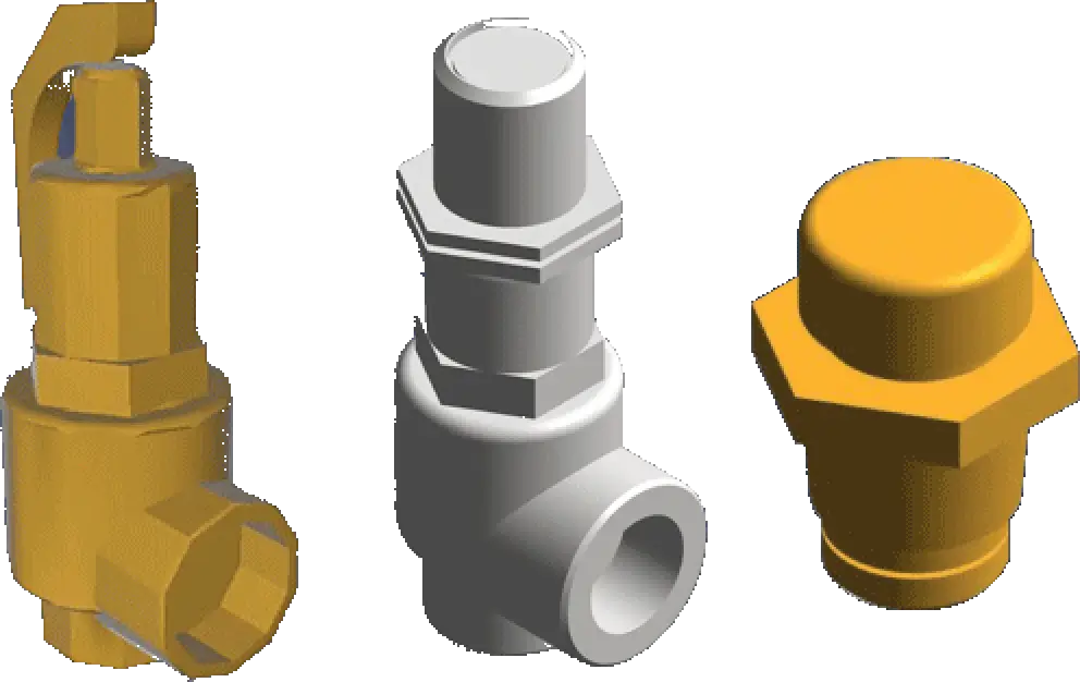
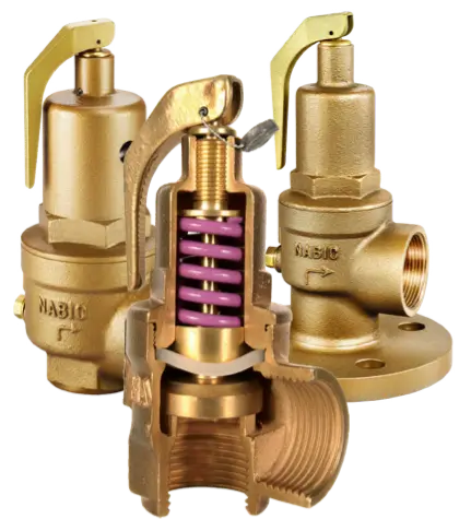
The function of the Safety Valve is to protect life and property against failure to control system pressures, ie it offers the last means of reducing system pressure before total failure.
Within heating and chilled water systems, excessive system pressures are caused by, amongst other reasons:
- During start-up of items of ‘plant’
- Failure of control valves
- Failure of temperature and pressure sensors within the system
- And of course human error
BS EN ISO 4126-1:2013 – Safety devices for protection against excessive pressure. Safety Valves.
This European Standard superseded BS EN ISO 4126-1:2004 which again superseded the older British Standard BS 6759. BS 6759 was divided into 3 sections;
- BS 6759 – 1:1984
- Steam and Hot Water
- BS 6759 – 1:1984
- Compressed Air and Inert Gas
- BS 6759 – 1:1984
- Process Fluids
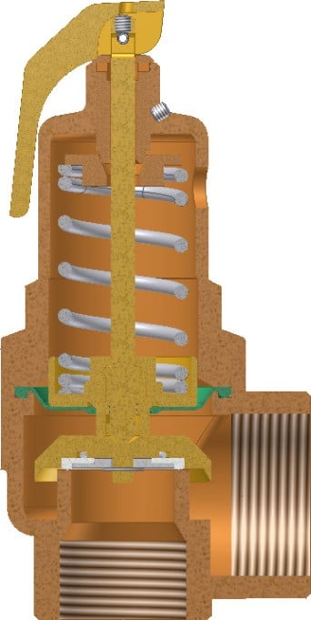
In 2004 the new, well new in 2004, EU Standard brings together the Safety, Pressure Relief, Safety Relief Valves into a single Standard – Safety Valves. Interestingly, the American Standard ASME / ANSI still divide these three functions. Due to the potential risk to life caused by failing systems, most nations around the world have a National Standard covering Safety Valves.
SAFETY VALVE OPERATION
Safety Valves used within the Building Services Industry follow a design that uses an applied force (a spring) to directly oppose the system force.
This valve design utilises three states:
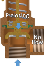
- Equilibrium
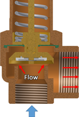
The equilibrium state is where the closing forces, ie applied by the spring and any back pressure, is in ‘equilibrium’ (balanced) with the opening forces, ie applied by the system pressure. The disc and seat are ‘just’ in contact so flow has not started but about to start
2. Fully open
The fully open state is where the valve can pass the maximum capacity at the specified overpressure. It follows of course, that for the valves to open, the system force must exceed the equilibrium force, ie overcome the applied spring and back pressure force.
Some designs of Safety Valve, like the NABIC Figure 500, achieve a higher discharge flow rate by having a higher disc lift and larger discharge size
3. Fully closed
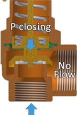
The fully closed state is where the valves is fully closed, ie nil leakage. The closing force exceeds the opening force, ie the opening force is lower than the equilibrium force
SAFETY VALVE SIZING
The sizing of Safety Valves is particularly important.
- Valves that are undersized will not be able to discharge the maximum capacity at the specified overpressure and as a consequence the system pressure will not drop but continue to rise.
- Valves that are oversized will not achieve the fully open state. The rising system pressure could only slightly lift the disc off the seat, releasing the excess pressure, allowing the valve to close. The valve starts a cycle of opening / closing as the design discharge was not achieved, this is often referred to as ‘chattering’.
NABIC have a sophisticated programme to ensure correct selection.

SAFETY VALVE INSTALLED POSITION
Safety valves should only be installed in a vertical position with the spring chamber, ie the bonnet, in an upwards position. An isolation valve between the safety valve and the system is strictly prohibited.
The installation should avoid:
- Long runs of pipework between safety valve and system
- Fittings and bends between safety valve and system
- Inverted safety valve outlet
SAFETY VALVE MAINTENANCE
- Testing
- A site risk assessment should establish a maintenance regime for testing the function of safety valves, we would specify that this should be at least every 3 months
- Inspection
- The NABIC design of safety valves allows for the internal examination and cleaning without altering the set pressure
- Re-calibration
- A site risk assessment should establish a period for re-calibration. In resent years, insurance companies and boiler inspectors have insisted that safety valves are re-calibrated on a yearly basis
TYPICAL SYSTEM FAILURES
Within Building Services, there are four typical system failure modes that bring the safety into action:
- Blocked outlets
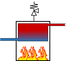
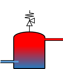
- External heat
- Uninsulated external pipe runs heated by external source, ie the sun
- Thermal expansion
- Failure of boiler temperature controls
- Pipework component failure
- Control valves failure
TYPICAL TERMS
Set Pressure
BS EN ISO state ‘The pressure at which the valve is about to open, ie the equilibrium state. In practice, it’s not possible to find ‘when the valve is about to open’, only when the valve is closed or just opened. ASME state ‘The pressure at which the valve starts to open’. In practice this position is easier to establish than the BS EN equilibrium position, ie ‘about to open’.
Overpressure
A pressure increase over the set pressure, usually expressed as a percentage.
Accumulation
The pressure increase over the maximum allowable working pressure of the system during discharge through the safety valve, expressed as a percentage of pressure.
Blowdown
The difference between the actual set pressure and the actual reseating pressure, expressed as a percentage of pressure.
Backpressure
The static pressure existing in the discharge system ‘from’ the safety valve.
Boiler
Water Heater / Storage
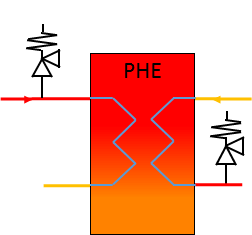
Heat Exchanger
